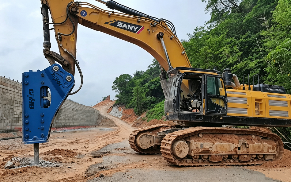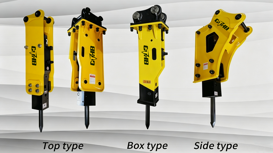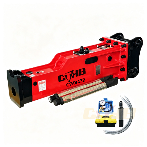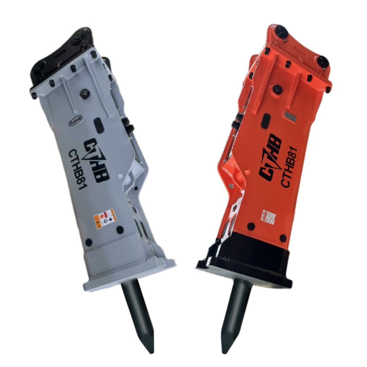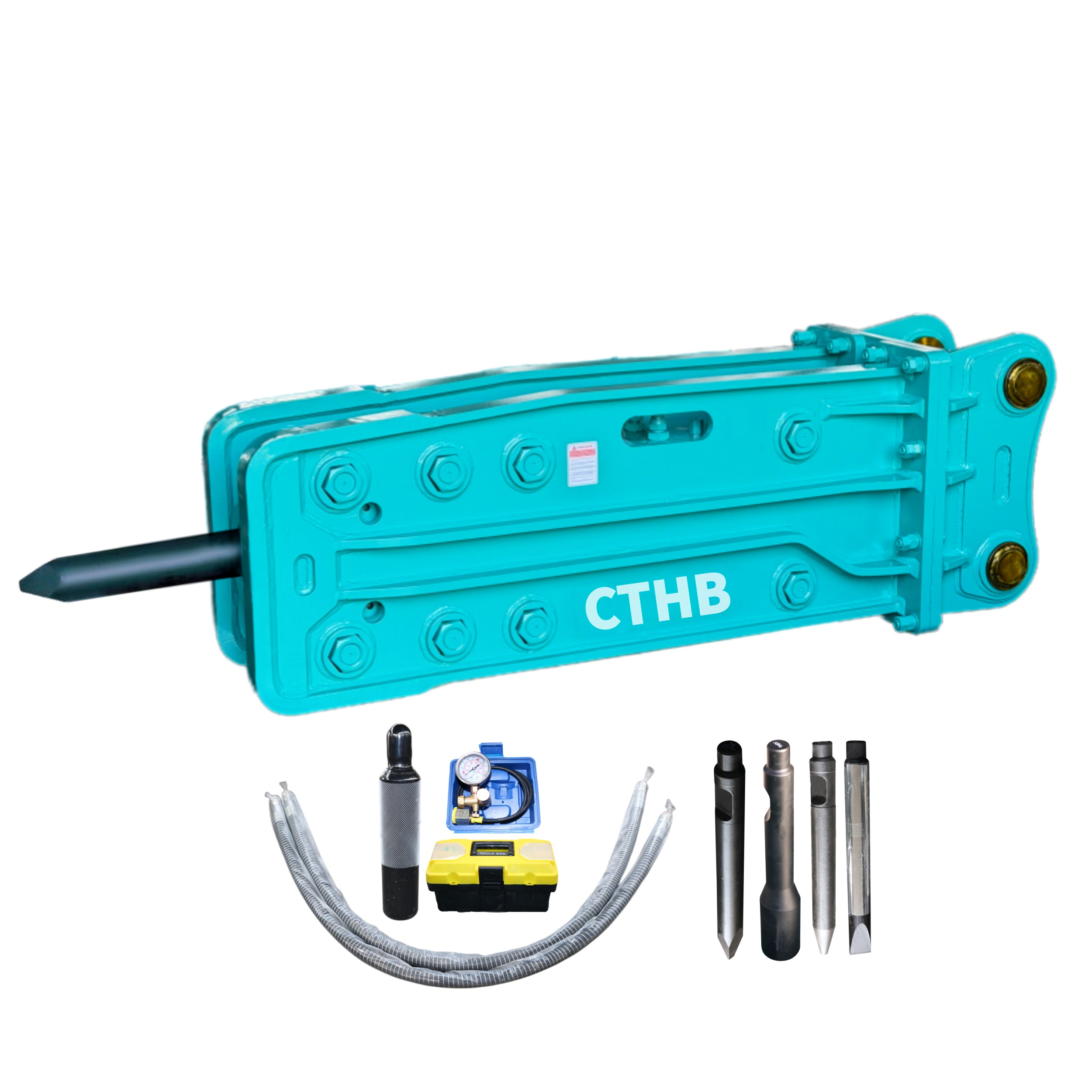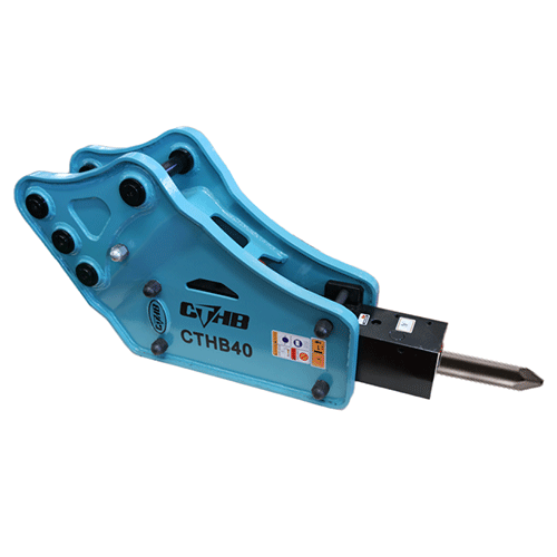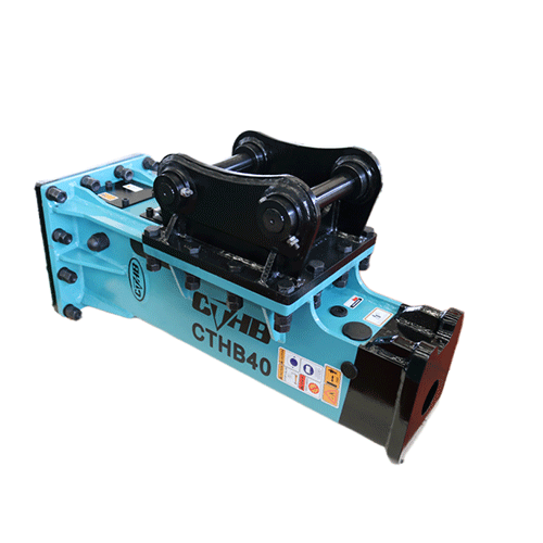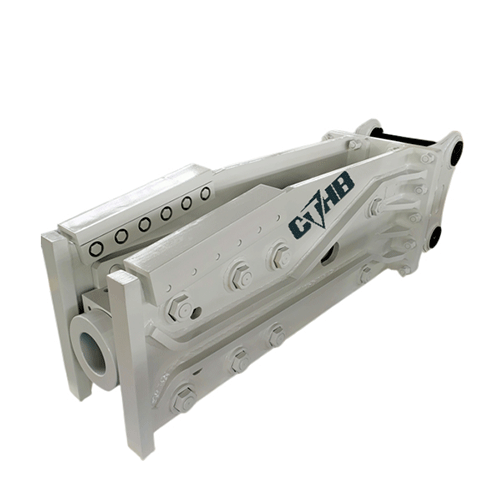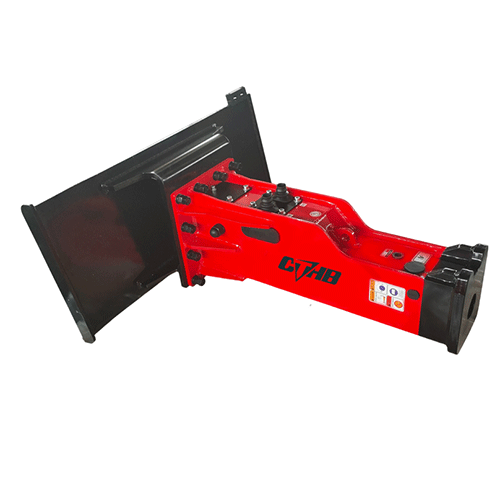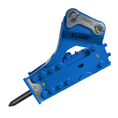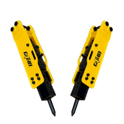
CTHB hydraulic breaker (also known as hydraulic hammer) is a high-impact attachment designed for rock breaking, concrete demolition, road renovation, and foundation excavation. Unlike standard excavator buckets, it relies on precise hydraulic pressure and rigid structural mounting to deliver powerful impact force.
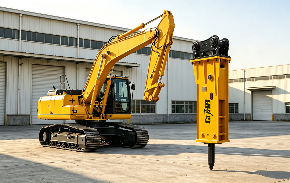
Why Proper Hydraulic Breaker Mounting Matters?
Mounting a hydraulic breaker onto an excavator is a precision task. Mastering the correct mounting method is the first step to safe and efficient breaker operation.Do it right, and you unlock maximum breaking power with minimal wear. Do it wrong, and you risk destroying your attachment, damaging your carrier, or causing a serious injury.
Step 1: Select the Right Breaker for Your Excavator
Before you even lift a tool, the most critical step is ensuring your breaker and excavator are compatible. A mismatched setup is the #1 cause of premature failure.
| Model | Chisel Diameter | Suitable Excavator | Hammer Weight | Operating Pressure | Operating Oil Flow | Blow Frequency | Oil Hose Diameter | Breaking Power | Auto Grease System | Back Cylinder N2 Gas Pressure | Accumulator Pressure |
| No. | mm | Ton | kg | kg/cm² | L/min | bpm | inch | kJ | ○ | bar | bar |
| CTHB05 | 35 | 0.5-1 | 91 | 90-120 | 15-25 | 800-1450 | 1/2 | 0.134 | ○ | 14-17 | / |
| CTHB10 | 40 | 0.8-2.5 | 102 | 90-120 | 15-25 | 800-1450 | 1/2 | 0.259 | ○ | 14-17 | / |
| CTHB20 | 45 | 1.2-3.0 | 120 | 90-120 | 20-30 | 700-1200 | 1/2 | 0.356 | ○ | 14-17 | / |
| CTHB30 | 53 | 2.5-4.5 | 196 | 90-120 | 25-50 | 600-1100 | 1/2 | 0.475 | ○ | 14-17 | / |
| CTHB35 | 60 | 2–5 | 254 | 90-120 | 25-50 | 600-1100 | 1/2 | 0.575 | ○ | 14-17 | / |
| CTHB40 | 68 | 4–7 | 302 | 110-140 | 40-70 | 500-900 | 1/2 | 0.661 | ○ | 14-17 | / |
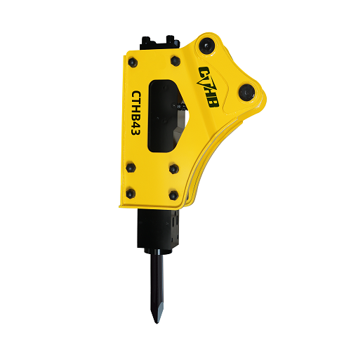
| CTHB43 | 75 | 6–9 | 408 | 120-150 | 50-90 | 400-800 | 1/2 | 0.756 | ● | 14-17 | / |
| CTHB45 | 85 | 7–14 | 733 | 130-160 | 60-100 | 400-800 | 3/4 | 0.935 | ● | 14-17 | / |
| CTHB50 | 100 | 10–15 | 982 | 150-170 | 80-110 | 350-700 | 3/4 | 1.564 | ● | 14-17 | / |
| CTHB60 | 125 | 15-18 | 1,727 | 150-170 | 80-110 | 350-700 | 3/4 | 1.877 | ● | 14-17 | / |
| CTHB70 | 135 | 17-25 | 1,862 | 160-180 | 130-150 | 400-800 | 1 | 2.668 | ● | 14-17 | / |
| CTHB81 | 140 | 18-26 | 2,054 | 160-180 | 120-180 | 350-500 | 1 | 3.196 | ● | 14-17 | / |
| CTHB81A | 140 | 18-26 | 2,149 | 160-210 | 120-180 | 400-550 | 1 | 3.204 | ● | 14-17 | 55-60 |
| CTHB100 | 150 | 26-30 | 2,217 | 160-180 | 150-210 | 350-450 | 1 | 3.758 | ● | 14-17 | 55-60 |
| CTHB121 | 155 | 28-32 | 2,717 | 160-180 | 180-240 | 300-450 | 1¼ | 5.014 | ● | 17-20 | 55-60 |
| CTHB131 | 165 | 30-35 | 2,912 | 160-180 | 200-260 | 250-400 | 1¼ | 6.974 | ● | 17-20 | 55-60 |
| CTHB140 | 165 | 32-38 | 3,202 | 160-180 | 210-270 | 250-380 | 1¼ | 7.052 | ● | 17-20 | 55-60 |
| CTHB151 | 175 | 37-45 | 3,902 | 160-190 | 210-290 | 200-350 | 1¼ | 8.153 | ● | 18-22 | 55-60 |
| CTHB185 | 185 | 45-50 | 5,902 | 205-245 | 220-270 | 180-200 | 1¼ | 13.255 | ● | 22-25 | 55-60 |
| CTHB195 | 190 | 48-55 | 6,602 | 225-265 | 270-330 | 180-200 | 1¼ | 15.521 | ● | 25-28 | 55-60 |
| CTHB210 | 210 | 60-75 | 7,252 | 245-285 | 290-350 | 150-180 | 1¼ | 20.435 | ● | 25-28 | 55-60 |
*Caption: spec chart comparing excavator weight, hydraulic flow (L/min), and pressure (psi) against breaker requirements.
You need to check three key specifications against your excavator’s capabilities:
| Specification | What to Check |
| Excavator Carrier Weight | The breaker must match your excavator’s operating weight class (e.g., a 20-ton breaker for a 20-ton machine). |
| Hydraulic Flow (L/min) | Your excavator’s flow must fall within the breaker’s required range.
Too little = weak hits. Too much = overheating. |
| Operating Pressure (kg/cm²) | Confirm your machine’s max pressure does not exceed the breaker’s rated pressure. |
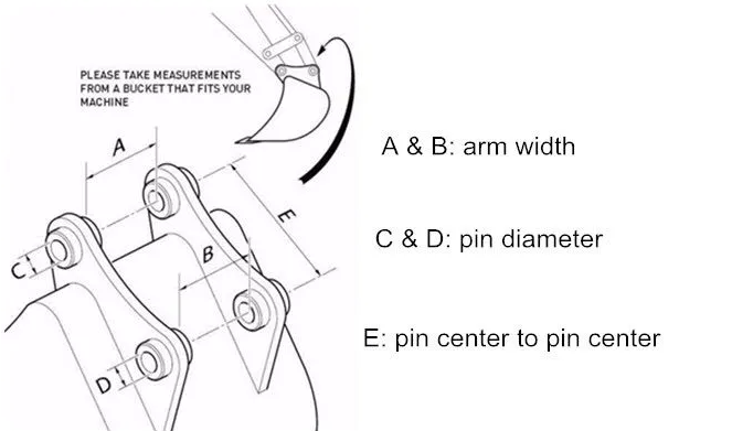
Tip: Also verify the arm width, pin diameter and pin center to pin center.Even if the weight is correct, physical dimensions must align perfectly.
Step 2: Prepare the Worksite and Equipment
*Position the excavator on stable, flat terrain. Engage the parking brake and place wheel chocks.Shut down the excavator completely.
*Depressurize the Hydraulic System: This is critical. Move the joysticks and auxiliary pedal controls in all directions for 30 seconds after the engine is off. This releases trapped pressure, preventing dangerous oil spray when you disconnect hoses.
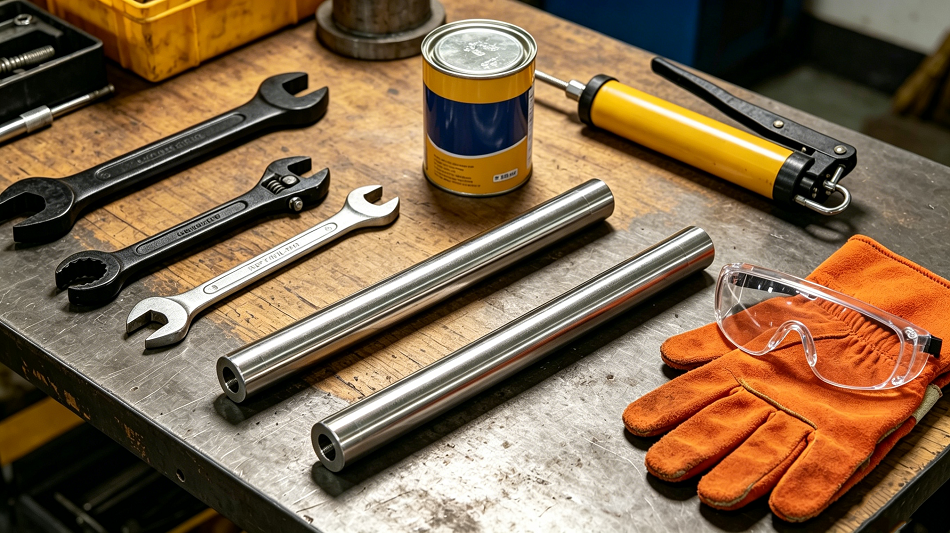
Gather Your Tools: Breaker mounting pins (upper and lower);Heavy-duty wrenches and a torque wrench;Grease gun and high-quality grease;Safety gloves and impact-resistant goggles.
Step 3: Physical Mounting – Attaching the Breaker
- Remove the Excavator Bucket.Position the bucket flat on the ground.
- Remove the two pins connecting the bucket to the arm (stick) and the bucket link (linkage).
- Align and Pin the Arm.Grease the bushings before inserting the pins to ensure smooth operation and prevent premature wear.
- Attach the Linkage: Extend the bucket cylinder and align it with the bucket link hole on the breaker’s bracket. Insert the second pin to secure the bottom of the breaker.
- Secure this pin with its retaining hardware.Tighten all hardware to the specified torque.
Step 4: Connecting the Hydraulic Hoses
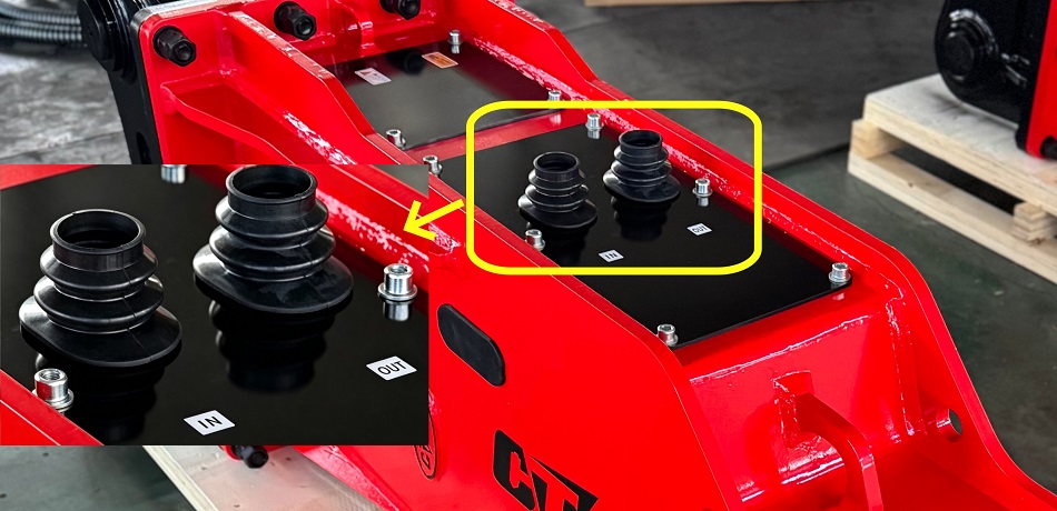
*Caption: A labeled diagram showing the “IN” (High Pressure) hose on top and the “OUT” (Return) hose on the bottom.
With the engine still off, connect the hydraulic hoses from the excavator’s auxiliary circuit to the corresponding ports on the breaker.
Important: Keep all hose ends and couplers absolutely clean. Dirt in the hydraulic system is a silent killer of pumps and valves.
Check for Leaks: Make sure all fittings are tight and secure to prevent hydraulic fluid leaks during operation.
Step 5: Install the Breaker Chisel and Auxiliary.Lubricate the Chisel.
Install the chisel on the front of the hydraulic breaker, fix it with retaining pins and spring clips, and confirm the chisel moves flexibly without jamming.
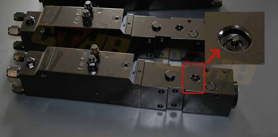
Before testing, you must lubricate the moving parts inside the breaker’s front head.Locate the grease nipple on the lower front head of the breaker.Attach your grease gun,inject grease and lubricate the chisel shank.
Step 6: Final Inspection and Testing
- Check that all bolts are tight, pins are secure, and there are no hydraulic leaks.
- Start the Engine: Fire up the excavator and engage the auxiliary hydraulic circuit.
- Warm Up the Oil: Run the breaker at low RPM for 2–3 minutes to warm the hydraulic oil to its operating temperature (ideally 50°C–60°C).
- The “Wood Block” Test: Place a thick hardwood block on the ground. Press the chisel firmly against the block and fire the breaker for 10 seconds.Listen for unusual noises and check for leaks at the hose connections.Watch for abnormal vibration in the hoses.
*Once all checks are passed and the breaker operates smoothly without leaks or unusual sounds, the installation is complete and ready for work.
Excavator Hydraulic Breaker Safety and Maintenance
Mounting your breaker correctly is only half the battle. Safe and efficient operation is the key to longevity.
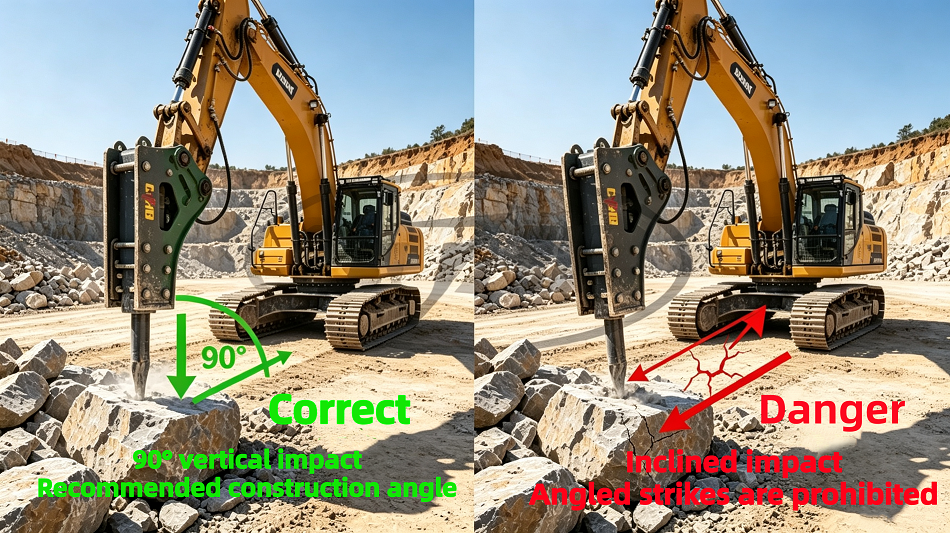
*Caption: A diagram showing the correct 90° striking angle versus a dangerous angled strike that could snap the chisel.
Never “blank fire” the breaker (operating it without a material to strike). This sends shockwaves back into the piston and causes catastrophic internal damage.
Maintain a perpendicular angle between the chisel and the work surface to avoid damaging the chisel or the breaker housing.
Do not strike the same spot for more than 15-30 seconds. If the material doesn’t break, reposition the breaker to prevent overheating.
Final Thoughts
Mounting a hydraulic breaker on an excavator is a systematic operation that integrates safety, precision, and standardization. Strictly following pre-installation preparation, standardized mounting steps, and post-installation testing can effectively avoid equipment failures and safety hazards. A professionally installed hydraulic breaker can maximize demolition and breaking efficiency, reduce equipment maintenance costs, and improve overall construction progress.